I have a new copilot on the project! Grace is a rescue that came to us this week, she is a real sweetie. She's a 7 year old black lab. Full of energy and keeping the birds and bunnies on their toes.
Over the past 10 days or so we've made a lot of progress in wiring. I came up with a solution for disconnecting the wing wires and eventually got it implemented. You can see the black D-Sub connector (looks like a printer cable connector) in the front lightening hole in the pic below. This allows me to not only remove the fuel tank if needed, but also the wing, without having to cut wires.
Another view of the service loop. Note the gold Comm Two antenna wire laying at the rear of the head rack on the right side. The antenna will be mounted right in front of the pulley you see. The wire runs down and back behind the baggage compartment to the Comm Two remote mounted radio.
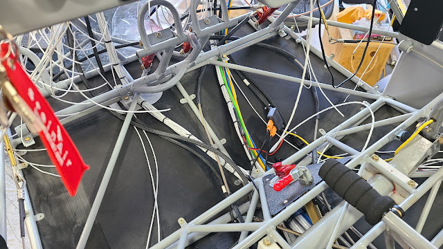
Here is a shot of the wiring bundle from both sides as they come down from the wing and transition to the center of the fuselage making their way forward.
The wire bundles making their way forward under the control column.
All the wing wires up to the firewall.
The two wing wiring bundles exiting the firewall area hanging and ready to be sorted.
With all the wiring now up to the firewall it became apparent that the size of the bundle in the center (previous pic) was too big causing interference with the brake lines on the pedals. So another day of undoing some of the previous work to reroute to either side of center was in order. This freed up the center section and allowed free movement of the brakes.
All the wiring re sorted into two bundles and routed off center. Laced up and finished. The other remaining wires will be laced separately later.
Still looks like a rats nest but a lot of sorting has happened. Hopefully a few more days of connecting and it will be finished, at least until the engine is mounted. A lot of lacing will be going on over the next week to tidy up everything as it progresses. Then all the engine electrical will have to be done. Getting closer...
Another ongoing project are the Butt Ribs, they close out the wing and give a finished look. Here is a pic of the Butt Rib cutout for the wires and fuel tubing. The fuel hose is not long enough, I was using it to establish the cutout for where it connects to the tank. Notice the AOA and Static lines are routed and finished.


