Wednesday, February 24, 2021

Brake Progress

Another concurrent project has been the Beringer brakes. As an upgrade to the standard Matco brakes, there are some extras that need to be considered. As previously mentioned the Beringer system came with a proportioning valve and a parking brake. Both of which required some head scratching to figure out mounting options.

Finally got it figured out and got all the lines made up and temporarily installed as well as the custom brackets. I had been waiting on some extra different fittings to make it all work, they finally came in and worked as expected. So, I will be final installing everything this week, then filling, bleeding and testing.

This was the initial way I had run the brake lines until I realized I needed to criss cross them so they wouldn't bind when flexing as the gear strokes. This way, I couldn't have enough slack in the line to accommodate that flexing. Plus, the fittings are much more exposed.

Here is a shot of the caliper quick disconnect. It will allow me to take the wheel/tire off or change brake pads, all without having to crack the brake system. The quarter turn quick disconnect is a lossless connector that won't leak or allow air into the system, pretty slick.

Another shot of the quick disconnect...

Here is a shot of the final position of the proportioning valve/bracket and parking brake/bracket with the new lines temporarily attached. That gray tube above them is the flap handle in the down most position.


This is the 45 degree bulkhead fitting exiting the fuselage bottom by the landing gear attachment. The line running upward is from the parking brake.

Here you are looking down onto the proportioning valve and  parking brake. This is the area between the seats. The flap handle was raised out of the way for the pic. Nothing is final installed at this time, just mocked up for fitment.

Here is a shot from behind the front gear mount looking forward. It shows the two brake bulkhead fittings through the fabric set in the criss cross position. There are two 45 degree brake line fittings that screw on to these bulkhead fittings.
 

More photos of the completed system soon...

Tuesday, February 23, 2021

Visit to Terry's Kitfox

Paul and I drove down to DVT to visit Terry and watch him start his Kitfox for the first time. Unfortunately, Terry had a few (to be expected) problems and we ran out of time and had to leave before the big event. Before we arrived, Terry was putting antifreeze into the system and had a leak, into the cockpit. He go it stopped and drained but had some clean up to do.

When we arrived, they (Terry and his Rotax mechanic, Rick) were doing the required burping of the oil system. We watched and they got it completed. They tried turning the engine over and were not getting any spark to the engine. After some discussion, they figured out the engine was not grounded and had to go to the aviation department at Auto Zone for a ground strap. Upon returning and installation of the ground strap they started the fuel pumps and had another leak. That leak was going to take some time to fix and unfortunately we had to leave. They persisted and eventually got it to start with no more leaks. Awesome! Congrats Terry, that is a big milestone. Next up, final inspection and the beginning of the Phase One 40 hour fly off.

Here's a quick video while we were there...


 Here is a video Terry sent me of the big moment...

Thursday, February 18, 2021

Firewall and Motor Mount

I worked on final shaping of the firewall today. It needed quite a bit of grinding to get it to shape. Actually, I used a 36 grit flap disk and went to town. The object is to get the curve of the top of the firewall to be flush with the Lexan windshield. Or, as close as possible which is what I did. The fiberglass piece you see in the pics gets covered over by the boot cowl later anyway, so close is good enough.

The other task was to test fit the motor mount. This required quite a bit of reaming but it fits fine. Got all the bolts, nuts and washers on and tightened down. Looks pretty good. Won't be long now...

Tuesday, February 16, 2021

Brakes, Flap Springs, Antenna Wires

Had a break through today, pun intended. I made a modification to my original bracket for the proportioning valve to make sure no contact could be made with the seat frames. It required drilling and filing the part that stuck up about the seat rails. Now, there is absolutely no way the seat frames can contact the bracket.

The break through came when I figured out how to mount the parking brake unit. Some times you just have to dump out the scrap bin on the floor and sort though it. I found the perfect piece of scrap to make the mount from. It was some angle aluminum that was wide enough to be the mount. After a lot of cutting, shaping, filing, drilling and sanding I had the part. I mounted the parking brake to it and then mounted the assembled piece in the fuselage. Works perfect. Simple is better.

Hopefully, all the new fittings I have on order will allow me to mate everything up. If so, I'm nearly done with the brakes.

This afternoon I received my new flap springs. The factory springs are too long and consequently they are weak and allow the flaps to droop when on the ground. The factory's solution is to cut 1.5" off the spring and bend a new hook. I tried that with unsatisfying results. So I went on an internet mission to find a replacement spring which I did. They arrived today. I quickly installed them and hooked up the flap cables to give them a try. They seem to work great plenty of power. I'll know more when I get the flaps installed. NOTE: The spring I found is exactly the same wire diameter and outside diameter as the factory spring, it's just 6.5" long vs 8.75". Again, the factory recommends cutting at least 1.5" off theirs making it 7.25". So, mine is .75" shorter.


40 degrees of flaps

The other parts that arrived in the mail today were the quick disconnect for the brake remote mount reservoir. Really nice piece, allows disconnecting the brake line from the reservoir without leaking or requiring bleeding of the brakes.

I painted the D-Sub brackets for the wing.

Last but not least, I ran the antenna wires to the transponder ground plane and connected the Com2 antenna to the unit. I had forgot to do this when we installed them so I had to cut some zip ties and re-zip them into the cable bundle running down the center of the fuselage. I also routed the antenna wire for the Com 1 radio from the upper left rear of the skylight area forward and down the windshield pillar on the pilot side.

Gold wire running up to and connecting to the remote mounted Com 2 radio. It will get laced onto the white wire bundle also.
Transponder ground plane antenna connection.

Monday, February 15, 2021

Beringer Brakes, Jury Struts and Landing Lights

Yesterday, I mocked up a bracket for the Beringer Proportioning Valve. I relocated it between the seats in an effort to simplify the installation. It looks like it will work out ok in this position. I've ordered some different banjo bolt fittings and will know when they come in. Then I'll focus on the parking brake unit. I set a seat frame and cushion in to check fit and it looks ok.

This morning, I wanted to get the jury struts mounted to the wing struts. Besides getting them attached, I didn't want to screw up the powder coat. Got it done without a scratch.

Up next, I mounted the landing lights. Again, the object was to get them mounted without scratching up anything. Done and connected.


Friday, February 12, 2021

Wing Adjustments, Wing Tanks, WIring, ECU

I've been at a stand still for a couple of days because I can't lift the tail by myself, at least not high enough to get it level. Today, with Chris's help, I was able to lift the tail into a level flight attitude.

I had previously set the wing tanks and compression tubes in but not tightened anything down because I needed to make some final adjustments on the wing first. Chris and I got side tracked and started brainstorming the wing wire routing as I was supposed to have this already done. However, I had several questions and wanted to wait for his input. This was a bit of a puzzle and proved to be interesting too. After working on it for some time we finally came up with a good workable solution and Chris got to work on the left wing wiring and laced it up. The exit was good, we double checked that we had enough of a service loop by swinging the wings into the folded position without stress. Additionally, we were clear of all the fuel line entries and exits.

That's when it hit me that the tanks were not finalized and bolted in. The wires were in the way of bolting the tanks in so, I had Chris stop and told him I would finish mounting the tanks later today and we could resume tomorrow. So, I had to undo some of what Chris had done to pull the wire bundle out of the way so I could work on the tanks.

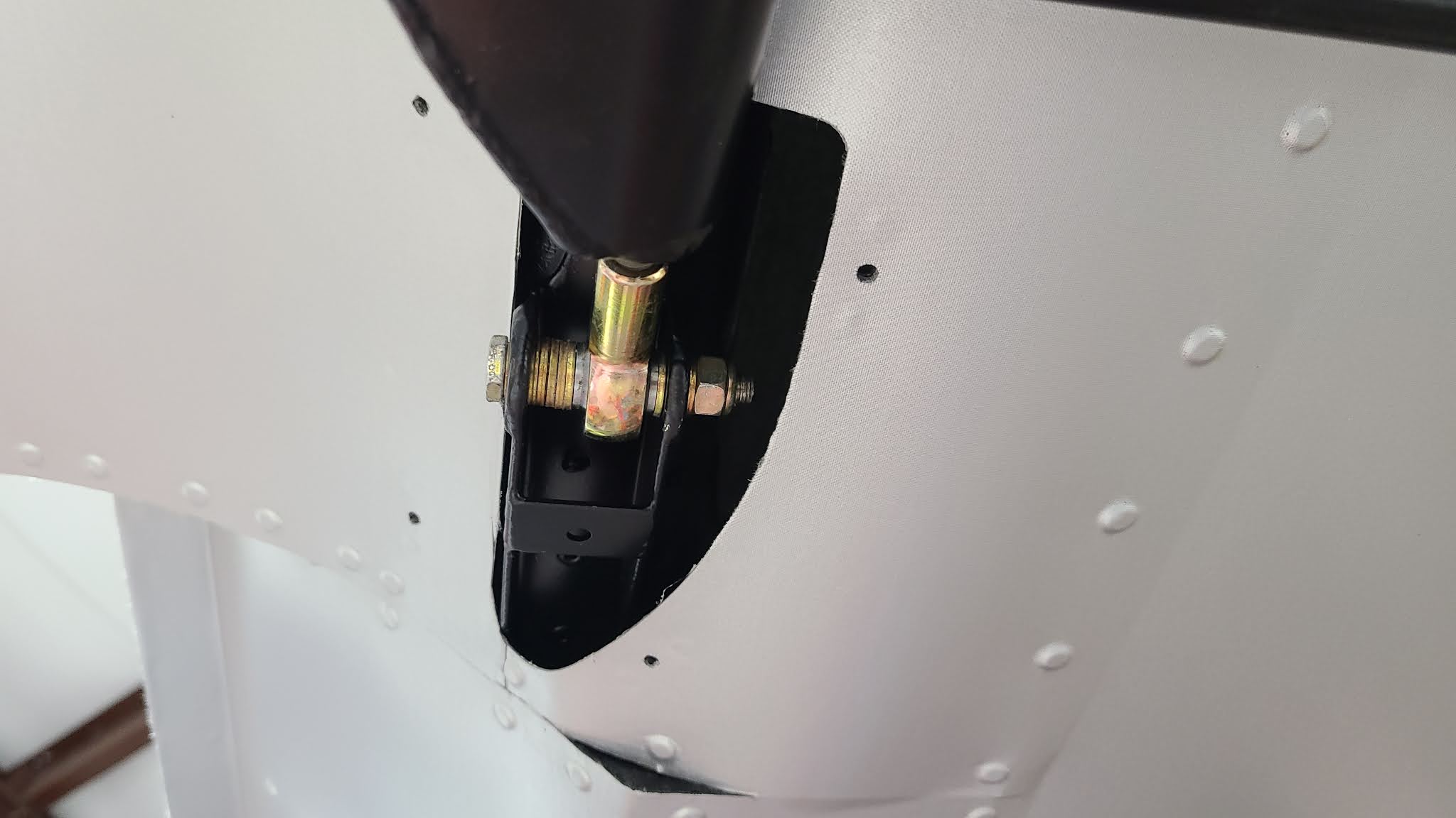
However, there was another task I needed to complete first. I needed to adjust the trailing strut rod bearing on the right wing. The wing adjustments needed to be finalized before mounting the wing tanks. That is why I hadn't bolted them in. When I put the struts on the wing before mounting I wasn't able to set the rod end correctly. So, with the wings finally in level attitude I was able to support the left wing while lifting the right wing to take the pressure off the bolt so I could remove it and adjust the rod end bearing. Once adjusted, I was able to relieve the pressure enough to reinsert the bolt with the proper spacer washers and tighten it for good. I had to preform the same procedure on the left wing. Now both wing struts are adjusted and have been final torqued.

Right Wing Rod End Bearing with washer spacers

Left Wing Rod End Bearing with washer spacers

Not really exciting but crucial. 

Now I could get back to installing the wing tanks. It is a trial and error proposition. The object is to get the compression tubes, that the tanks bolt to, to be level with the flanges on the tanks. NOT level with the ground. Each compression tube bolts in two places, fore and aft. There are washers the are placed under or over each end of the tube to accomplish this leveling. One places the washers fore and aft, in the quantity that looks sufficient, mount the tanks to see if the flanges sit level on the tubes, if not, pull the tank out and try again. This goes on until the flanges and tubes have no gaps, or as close as possible. The reason for this circus is so no warp or twist is induced on the tanks when bolted in, preventing stress and leaks. It is a time consuming task preformed while balancing atop a ladder reaching over the wing, lifting the tanks in and out multiple times, three time each side to be exact. NOT a good time. I also didn't snap any action pics of this. However, it is done, the tanks are mounted.

I was able to get the left wing tank installed and rerouted the wiring back into the position that Chris had it. That's when it hit me, if I have any problem with the tanks I won't be able to remove them without cutting wiring. Not good. I called it quits for the evening after getting the right wing tank installed. I would get the left one tomorrow.

This morning I got the left tank leveled and installed while waiting for Chris to show up. When he arrived, I told him about the problem of the wire routing and tank removal. I originally had expressed a wish to be able to remove the wings without having to cut wiring. Way back when, we gave some thought to it and I actually purchased some cannon plugs in an effort to develop a way of splitting the wires at the wing. I eventually abandon the idea and moved on to other construction tasks.

So, here we were again and I had spent last evening thinking on it again. I came up with the idea of a D-Sub connector, like a printer plug, and wondered if it might be a workable solution? We talked about it and agreed that not being able to remove the "removable" wing tanks without cutting wires was a problem. After some discussion and fiddling, we set about making a bracket for a D-Sub connector and mounting it. It seems to be a workable solution providing a way to not only remove the wing tanks but the wing itself without cutting wires. That is huge. I gave Chris the go ahead and he cut the wire bundle and started preparing it for the D-Sub connector.

First attempt for the right wing with 1/2 of the connector in place, had to order the mounting hardware.
Without the connector
The larger one is the second iteration for the left wing.

A couple of shots of the wires in the connector on the right wing. The above bracket is not installed yet nor are the wires weather proofed. The above bracket goes to the right of the plug in the pic, you can see two small screw holes between the large lightening holes that the bracket uses. To the right and up at the top of the rib, you can see the two side by side holes in the tank, one for a vent and the other for the fuel gauge tubing. Note: the butt rib is not in place in these pics. You can see the stand offs for the butt rib, the gray vertical ovals with two screw holes on each end of the rib

The last project for today was to fab a tray for the engine ECU and temporarily install it. It's pushed back to allow for the large cable that attaches to it. This will allow some flexibility in routing the cable though the firewall. It also can be swapped to the other side of the fuselage or, it can be mounted upside down if necessary.