Behind the scenes I've been planning my instrument panel for the better part of a year. This is a multi-phase project that is not part of the kit. It is also no trivial matter considering the potential expense, especially if you've never done it before. Early in the process, the kit builder has to decide on a panel budget and what is required, desired, needed, wanted, etc. Every kit builder goes through this process. Now it is my turn, thank god for the internet.
At Just Aircraft, they are big advocates of building the SuperSTOL and Highlander as light as possible with few (if any) modifications. To this end, Troy has one of the most minimal panels I've ever seen in his SuperSTOL XL demonstrator with only a couple of instruments and a radio. Some of the "Build Assist" guys echo the JA mantra, build light. The thinking is, the lighter the aircraft, the better the performance. So which is it, simple (less expensive, less capable, lighter and easy to install), or "Glass" (expensive , more capable, heavier
and harder to install) or something in between? It comes down to mission and capability. Each kit builder must define the type of flying that they will do and how much they're
willing to spend, and then back into the best panel for the money that will suit their needs.
After much deliberation, research, discussion, and more research, I decided I was more interested in capability than counting grams. I would sacrifice some performance (at least initially, refer to the engine section) for more capability. Consequently, a glass panel with as much capability as possible for the least amount of money was desired. Now for more research, what products were on the market, what was coming soon, how do the products and manufacturers rate? Which products would accomplish my goals the best? Which company? There are many companies to choose from and all put out excellent products with loyal followers. However, two major players emerged with product lines that I would consider, Dynon and Garmin.
Initially, I had chosen Dynon and their "Skyview" system. They had glass panels, small radios, intercoms, auto pilots, etc. They are a small innovative company that has been supporting the experimental aviation market for decades with thousands of their units installed. They put out a great product, have a great support mechanism, great customer service and continue to advance their product line. To me, they are a bottom up company, meaning they started out in the experimental market and are now moving up into the certified market. I think this is a tough road for them but they are making it happen. They also have extremely loyal and enthusiastic customers which I think is a testament to their products.


On the other hand, Garmin is a very large top down company in the sense they started in the certified market decades ago and are now moving down into the experimental market. This is a much easier transition for Garmin because of lesser restrictions and their large size. Garmin also has an excellent reputation for support, service and quality products. Being that they have been in the certified market for so long, their products are required to work at a much higher level of reliability. Ultimately, the fact that they are heavily into the commercial and general aviation certified markets swayed my vote. I also took notice of the large number of small aircraft manufactures that were using Garmin products in their planes, such a Carbon Cub.
Finally, I reached a point in the build where I had to commit to Dynon or Garmin and buy some servos for installation. Upon doing some more research on the competing products, I came to the conclusion for the reasons stated above that I would go with Garmin. At this point, I had already invested several months of research and
drawing time into Dynon Products and had several iterations of panels
designed with
their products. Now I had to start over with Garmin and bought their auto pilot servos for immediate mounting in the plane.
Garmin has a G3X display which is a large screen (10.6") that is very capable and is the flagship in their "experimental" product line. This is the major component that you build the rest of the panel around. It was an easy pick given its size, resolution, capability, and reliability, matter of fact, I'll take two! Whoa, not so fast! Will these even fit in my SuperSTOL? Some more research is in order. If you are not familiar, the SuperSTOL presents a pretty big problem for
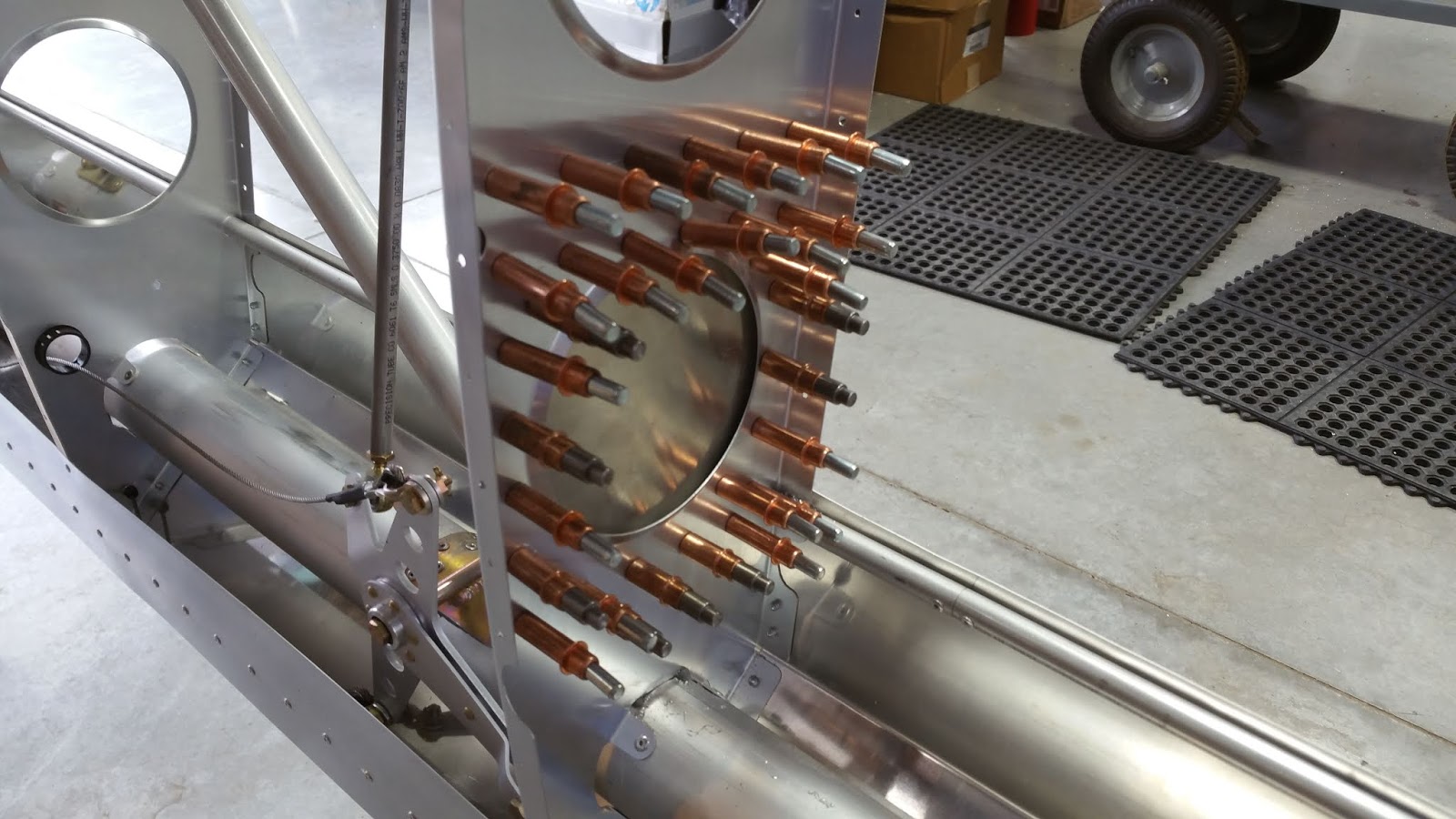
mounting instruments. There is a truss for the landing gear that runs
side to side from the upper gear mounts on each side of the cabin. It
is there to absorb the shock of the high performance SuperSTOL landings.
Anyway, this truss is right in the way of panel mounted instruments,
gauges, buttons, radios, etc. and determines the placement of everything in the panel. So, when choosing components, the truss has the last word
on placement.


I was able to locate and download the Garmin G3X Installation Manual from Garmin's web site. I located the section with G3X dimensions so I could determine how to make it fit. Would it go in front of the truss or would it have to sit on top of the truss? Although this doesn't sound like a much of a problem, if it had to sit on top of the truss, it would mean I could only have one screen instead of two. A single screen would have to be installed on top of the truss in the center, raising the panel height to the point where the pilots couldn't see over it. Although I've seen other panels that have done it this way, it really wasn't an option for me. So, I needed to find a solution to fitting two screens in front of the truss. I eventually figured out that I could move the panel itself forward a couple of inches allowing the bottom part of G3X to slip between the panel and truss. The units would still have to sit higher than I would like because of protruding connectors on the back of the units. However, they could sit down enough to allow the panel to sit at the same approximate height as a stock panel. This would allow both pilots to see over it. With that problem solved, I now had to determine what else I "needed" to make the G3X's work.

This is where companies like SteinAir come in. They specialize in building "custom panels" for kit builders. They sell all brands of aviation gear and most importantly for me, Garmin. They will do as little or as much as you want, all the way up to a complete bolt in panel. They can laser cut/water jet panels, laser etch text, do carbon fiber or aluminum panels, mount everything, assemble wiring harnesses, etc. They are extremely knowledgeable and help builders navigate the complexities of component selection. They can answer any questions with ease. Being that this is a rather complicated undertaking that can have disastrous consequences, both physically and monetarily if not done properly, I decided early on to go with SteinAir.
Even though I had a pretty good idea of the major components I wanted, I had no idea of all the background pieces required to make everything work. SteinAir identified all the missing components and even offered up some alternate solutions as well. They put together a package deal that includes everything, even a complete wiring diagram of MY system and a discount off the components. The wiring diagram would come in very handy should I ever need to spark chase. They have all the CAD/CAM systems in house to draw and cut your panel perfectly. They also have a loyal and enthusiastic following.

At this point, I am closing in on the final design of my panel, at least the major components. I have the various switches, buttons, etc. left to figure out. These remaining pieces to the puzzle are not related to the avionics but are instead related to the engine, batteries, lights, and other options. Although they are not directly related to the avionics, SteinAir will still plot and cut the holes for anything else required in the panel. I just have to figure it out and let them know so they can add it to the panel.
I requested SteinAir to laser cut an acrylic panel based on the above final design. Pretty cool. They laser etched all the controls, bezels, and knobs. This test panel allows me to verify the placement of the units by mounting it in the actual plane. I added some angle brackets to the top and bottom to make it rigid. I then made up some corner brackets to begin to figure out how I might mount the panel to the airplane. After clamping the panel in place, I began the process of verifying that all the components would fit planned.


I cut some one inch foam insulation to size to simulate the
thickness of the critical component (the auto pilot at the bottom of the
center stack). It is critical because the connector on the back of the unit must pass through the truss on the back side. I super glued an old 9 pin connector in the correct position on the back of the foam, then placed the foam behind the panel in the correct spot to
make sure it would clear without issue. Perfect! I used another long
piece of insulation to jam between the truss and the back of the panel
to simulate the thickness of the G3x's. Actually, I cut the long foam to
two inches wide and I only need one and a half inches for the G3X's to
clear. So, my plan is working out. Looks like everything fits as it
should, no modifications.


The last verification is to make sure the two other components (GTR200B Radio, and the GNX375 Navigator/Tranponder/ADSB IN/OUT) will fit. Both are long units, the 200B is the top component in the stack and is 9.75" overall in length. I cut more foam, an 8x6.25" piece to simulate the 200B box with another piece 2.5x1.75" in depth, simulating the connector on the back. This was super glued on the back. When this simulated 200B was put into place, a potential conflict arose as the length intersects with the cross tubes going to the firewall.