Thursday, September 10, 2020

Extreme Windshield

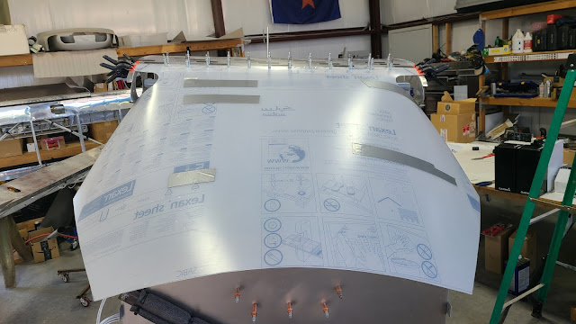
Over the past week I've been installing the Extreme Windshield. The first task which was accomplished previously, was to fabricate the Windshield/Skylight bracket and install the Skylight. It is necessary to have the Skylight installed (at least the forward edge cleco'd in place with the rest clamped) to help stabilize the bracket and to set the spacing of the windshield.

To begin the windshield installation I had to trim the aluminum side pieces to fit the fuselage and cleco them in place. The trimming was to clear welds on the fuselage, the length of the pieces was fine.

The next task was to use the provided template to cut the top of the firewall to shape. I decided to make a temporary Lexan firewall using my Titanium firewall as the template. This allowed me to "see" what was happening while making adjustments. It also would be less expensive to screw up, just in case.

Once I had the shape cut I set about fitting the inner boot cowl to the firewall. This inner boot cowl accomplishes a couple of things. First, it gives a surface for the front of the windshield to attach to. Second, it provides quite a bit of strength to the upper firewall. 

Originally, the Extreme Windshield was designed for the Highlander and the mold for the fiberglass inner boot cowl was made for it. When someone decided to mount this on the SuperSTOL they realized that because the SuperSTOL has a thicker wing, the angle of the front of the windshield was different and the fiberglass part needed to be rotated up to the new angle required. This means that the top of the SuperSTOL firewall would have to be bent out a few degrees to the new correct angle. It just takes some extra fitting/tweaking to make this work but once done the installation is the same.

As you can see from the pics, the fiberglass part is larger to allow for trimming. So, the object is to get the fiberglass part to be just about even with the Lexan shape. I got it close but realized the Lexan firewall was not allowing me to finish because of the required bend in the firewall. I decided to transfer the arc to the titanium firewall, re-install it and go from there.


After cutting the Titanium to match the curve, I measured and put the required bend in the Titanium then re-installed it on the fuselage. This is not a one time thing. It is a "get close" and try again proposition. The object it to have the windshield make contact with the entire top surface of the fiberglass part when installed. This is complicated by the fact that until you cut the windshield you can't know if it will make full contact. So, get it close and adjust if needed. 

Here is a pic showing the bend in the Titanium and the fiberglass part fitted to the Titanium. As you can see the shapes are a little different. First, the Titanium sticks up a bit over the fiberglass, this is so the windshield will be flush with the Titanium (it allows for the 1/8th inch thickness of the windshield). Second after everything is fitted, I will mark and remove the excess Titanium, sanding to the exact shape of the finished windshield.

The next phase was to lay the provided windshield template out on the Lexan and cut it out. Once I had the Lexan cut, I clamped it in place on the fuselage and squared it up with the leading edge of the skylight, leaving a 1/8th inch gap for expansion. When I was happy with the fit and position, I clamped it in place so I wouldn't move. I then drilled and installed cleco's all across the trailing edge of the windshield. This sets the position of the windshield for the rest of the fitting.

Then I used the firewall as a guide to draw a trim line on the Lexan. I trimmed it to that line and sanded from there to get it to fit in place without stress leaving a 1/16th to 1/8th inch gap. This is a curve and takes some time to get it right. Then beginning in the middle, I carefully drilled and cleco'd the front of the windshield in place working side to side.

The next part takes some strength as the sides have to forcefully bend into the channels on each side. First, you have to bend them down and clamp them to determine your trim line, otherwise they won't fit. Once trimmed, you can bend them and push the inside and behind the aluminum channels that were fit initially. Once happy with the fit you can cleco them in place. Then on to the rear upper part of the door opening. Same procedure, clamp in place and then trim. Re-clamp in place and drill for cleco's. Repeat for the other side.

Next up will be fitting the door trim pieces and figuring out what fasteners to use to finish up with the install.

Tuesday, September 8, 2020

Setback

Unfortunately I had a mishap this week. Everyday, I have to jockey the plane around in the shop so I can park the F450 in it at night. Every morning, I open up the shop and move the truck out so I can work on the plane. I have to unstack rolling carts etc., out of the way then roll the fuselage from its spot out into the bay. While doing this dance Wednesday morning, I had to make sure the rear of the fuselage was not going to contact the wings at the back of the shop. I grabbed the rear fuselage rotisserie and began pulling it out when the front rotisserie got hung up on some debris on the floor and before I realized it, it collapsed. The T leg punched through the fabric on the bottom of the plane underneath the pilot seat. Well, as they say, it could always be worse. So, I now have to patch the bottom.

If there is a silver lining it would be that I went with Oratex instead of Polyfiber. The Oratex is really tough stuff and had this been Polyfiber it would have ripped until it hit steel making a much bigger hole and consequently a more difficult patch. Also, I would have had to paint Polyfiber which means I would not only have to patch it, but repaint it. So, this is another reason to go with Oratex. I'll post pics of the repair when complete...


Friday, September 4, 2020

Back to Work!

Had a few days of milder temps that allowed me to get some work done. Had Chris come work on wiring and made a few more decisions. He got the headset jacks all wired into cannon plugs. 

Meanwhile, I worked on getting the final finish tape on the vertical stabilizer. I had to take the fuselage off the rotisserie so I could get the tape all the way down the back. Once done, I put the fuselage back on the rotisserie. I also made up some doilies for the rudder stops and the flying wire tangs on the bottom of the fuselage.

The next task was to install a couple of inspection ports on the tail for the elevator. These ports will allow easy checking of the elevator push rod nut attachment to the elevator. It also allows me to install the elevator which will be handy. I purchased these from the factory (a pair - one for each side). These were meant to be installed with the Poly Fiber fabric system, and would have been overlapped with fabric and glue kind of molding them into place. With Oratex, they would have to be glued on the exterior, not as secure. So, I wanted to come up with a way to make them more secure. I decided to make another set and use them on the inside of the fabric as a backer plate. After tracing them and cutting them out I drilled the holes for lock plates and dimpled the holes for flush rivets. I needed the pieces to "nest" flush so when installed they would sandwich the fabric providing a much more secure hold on the fabric. It worked well and I'm happy with the result.


I began by gluing the outside piece on the fabric in position using super glue. Once it flashed off and I was happy with the bond, I cut out the center section of fabric making a hole that I could insert the backer plate into the fuselage. I did have to cut a small piece out of the backer ring because there was fabric glued to fuselage structure. Once in place I used cleco's to align and hold the rings together. I then placed the lock plates in place using the same cleco's working my way around until all lock plates were temporarily installed. After riveting the plates in place, I moved on to the other side and repeated the process.

 
Once finished, I installed the Lexan covers I had cut out using the outside ring as a template.
The next day, I cut the holes needed for the elevator attachment. I still have to cut a slit or channel so I will be able to remove the covers when needed with the elevator attached. I'll ponder that and wait till I reinstall the elevator to decide how to proceed.

Next up, I removed the panel to get it powder coated, I also removed the side door panel that the panel attaches to. It is also out for powder coating. I had a little clean up sanding and rounding of corners with all four door jamb pieces. Before dropping all the pieces off, I had to drill and install lock plates in the top flanges of the panel to accept a glare shield. I didn't get any pics of that but will take some when the panel returns this next week.

Another small detail, after removing the panel and door jambs, I painted the shock mounting brackets that are welded to the fuselage. The door jamb pieces will be black and the outside pieces surround the shock mounts, so I painted them black to match.

Then it was on to the butt ribs. I needed to install lock plates to enable the removal of the butt plates later for powder coating. So, I drilled and installed them and screwed the butt ribs in place.


I built up the top windshield attach bracket. I had already fabricated the factory piece but since I changed to the extreme windshield, it required some modifications. I had to add a wide plate to provide a flange for the windshield and the skylight to attach leaving an 1/8" gap between them for heat expansion. This piece would rivet onto the factory piece making it much wider. Once it was cut and positioned, I drilled for lock plates and rivets. I checked for fitment and needed to bend the factory piece to align with the curvature of the Butt Ribs. Once bent into the correct position, I drilled all the lock plate holes required for both the top of the windshield and forward edge of the skylight. Then it was time to rivet the pieces together. Once done, I cleco'd it in place and began fitting the skylight to it. Since I don't have my wings on, I can't drill for the lock plates along the Butt Rib edges however, I can drill the front and rear edges. So, that's what I did on the front edge.

I left the skylight a little wider on the sides and longer in the back so I can trim it as needed. Oh, and obviously I'm leaving the protective film on both sides of the Lexan until I'm completely finished. 

I'll install lock plates and screws next. Phoenix is under an EXTREME HEAT ADVISORY for the next 5 days, 108-112 degrees everyday. Probably won't get much done for a few days...


Friday, August 21, 2020

AeroGraphics

I decided on some graphics for the fuselage. I ordered them from Aerographics. They were really easy to work with and had a quick turn around. I have several ideas and just started with the SuperSTOL logo down the side of the fuselage.

Today, I first leveled the fuselage head rack, then taped the logo in place to see where I wanted it. After futzing with it for a while, I was finally happy with the position. I measure up from the floor to the bottom of the first letter, then matched that in the rear to give me a level layout. I marked the fuselage with pencil registration marks so I place it back into position when ready.


I cleaned the side of the fuselage with a soap and water mixture and wiped it clean. I then wet the surface with the same Dawn/water solution, peeled the backing off the piece, sprayed it and then placed the piece into position. The soapy water solution allows one to fine tune the position the piece. Once in position I used a small plastic squeegee to wick the solution/bubbles from behind the piece. I worked from the center out front and back until most all of the solution was out. Then I slowly and carefully peeled the top layer off leaving the lettering behind. Once the top layer was off, I looked for and squeegeed any remaining bubbles from behind the lettering, gave it a final wipe off and left it to dry overnight.


It went on without a hitch and looks pretty good. Tomorrow, the other side...

Now for the other side of the fuselage. Following the exact same procedure, I set up to mount the logo on the passenger side. No issues and it went on just as smooth.


Wednesday, August 5, 2020

Instrument Panel Avionics Tray

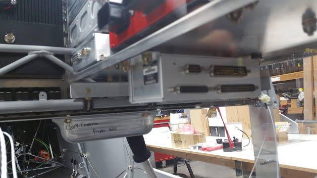
After much head scratching, I decided to go with a single tray from the Truss to the Firewall. I had several iterations of trays, different sizes and shapes before deciding on this one. I worked on laying out the components that need to be installed behind the panel. After discussing it with Chris (Wiring Guy), we both thought this arrangement was the most effective. It calls for the IBBS Backup Battery, VPX Pro, GAD-29, and the GDL-51R on the top with the GEA-24 on the bottom.

Once I finalized the order I set about to drilling the tray for the hardware.

Then mounted all the components.

It all mounted with temp hardware, I'll powder coat the tray before final installation.

I did goof up and switch the GLD-51R and GAD-29 when I drilled the holes. I will switch them before finishing. The GAD-29 allows more access to the D-Sub connector on the back of the GMC-507 Auto pilot controller.

I had the GO-40 CO detector left to find a place for. I ended up using the tabs that were already welded on the cross bracing. I cut out a plate and fitted it to the tabs. Since I wanted to use lock plates I had to install them on the plate, the tabs were too small to install the lock plates in them. Then mounted the CO detector on the bottom facing downward. I could have mounted it on the top side but the clearance to the glare shield (still to be fabricated) would be too tight. No harm in having it facing downward.


Tuesday, August 4, 2020

Panel WIring

Chris came by today to begin work on wiring the panel. He checked out my progress and studied the large wiring diagram I had printed out. Next, we began developing a plan of attack and started separating the spool of wires laying in the cockpit into common groups. Depending on where the final connection would be, we divided the wires either right side or left. 

Then he started wiring the USB connectors in the panel. Since these were so close to the Truss, he decided to solder the connections leaving a few inches of wire where we will add in line connectors. This will allow for easy removal of the USB connector from the panel. 

We then turned to the many switches. We had to figure out just how to wire them in series so we could use one of the dimmers to control the brightness.