Thursday, March 28, 2019

MOD – Split Rear Baggage Panel


I trimmed the upper rear baggage panel to give about 1/16th of an inch spacing between the upper and lower panels. I measured and cut a couple of stiffeners to be Hysol’d to the lower panel to act as a lip for the upper panel to rest on when in place. This serves double duty as a lip and as an attachment point. 

Once cut to size, I bent a half inch of the stiffener to 90 degrees effectively making an L bracket. I prepped both surfaces to be joined and Hysol’d them together. I placed a 48” level on them with a couple of 5lb plates on top to hold the pieces in place while they cure overnight. I will drill and install three lock plates to the lip once the Hysol cures. This will provide three more screws along the seam joining the upper and lower halves together.

MOD – Rear Baggage Access Panel


I covered the access panel and used stainless rivets to mount the latch mechanism to the door.


I mounted (Hysol) the striker for the latch mechanism. Don't know if this will work or not? I have my doubts about the Hysol sticking to the Delrin. I had some seat track material leftover and it was very close to the thickness I needed for the latch so I decided to give it a try. I sanded the aluminum where the striker was to be mounted and used a razor blade to score the back of the Delrin in a cross hatch pattern to give the Hysol something to grip. I also had some extra rubber drawer liner for my tool chests and super glued that on to negate any noise from metal to metal contact as well as to provide a little clamping pressure.

Tuesday, March 26, 2019

MOD – Auto Pilot Pitch Servo

Push Rod Fabrication and Installation

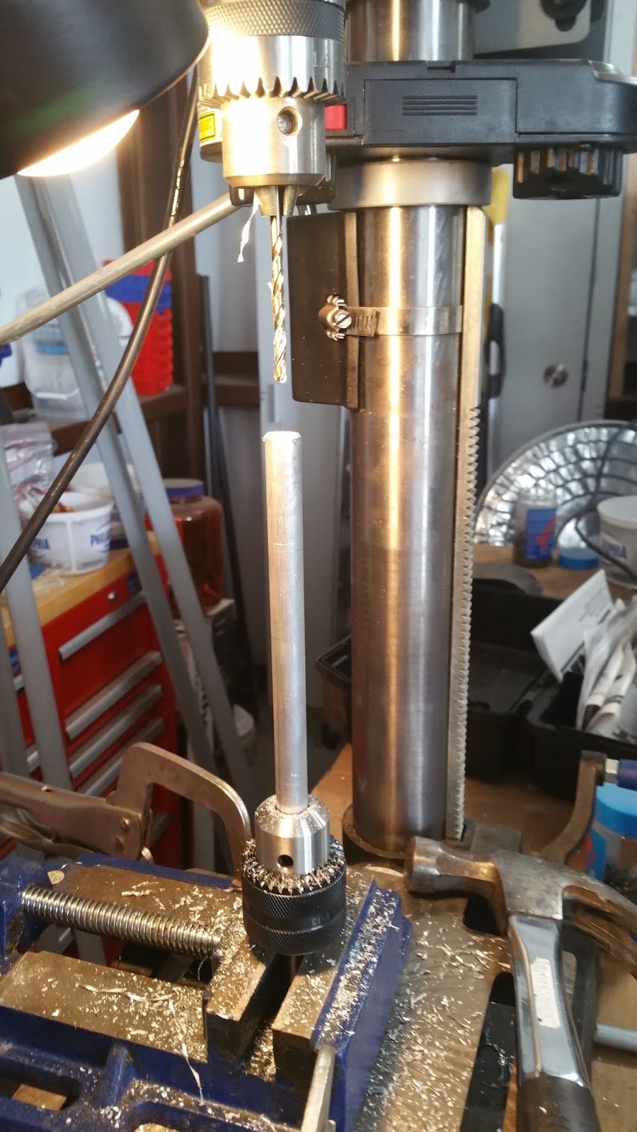
First off, I realize this is not the most accurate method to use and ideally, this should be done on a lathe. However, this push rod is not a rotating piece, just a push rod, so extreme accuracy is not required as it does not rotate. I did take care to align it as best I could and it came out very close.

Second, the push rod blank that was supplied with the Garmin Servo kit was not large enough to drill for a 1/4x28 aurora bearing. The Garmin kit came with a 10-32 bearing, the elevator bell crank has 1/4x28 bearings and would require another 1/4x28 bearing to mate up with the push rod. So, I needed a large enough aluminum rod to drill for 1/4x28 threads. I matched the size of the elevator push rod and purchased a ½” diameter aluminum rod. It came in a 36" length which I cut down to 8" for the push rod.

I used a lathe chuck to center the rod on my drill press. Inserted the centering bit in the drill press and began the drilling operation. Once a centered hole of sufficient size was started, I switched to the #21 bit required for the 10-32 tap. I drilled the hole to the appropriate depth for the 10-32 aurora bearing.

Once finished, I flipped the rod to drill the other end for the ¼ x 28 aurora bearing. Again, I began with the centering drill bit to start the hole and finished with the #3 bit. I then tapped the hole with the 1/4x28 tap, then tapped the other end with the 10-32 tap. I test fit each aurora bearing to ensure proper depth and fit.
 
Once both aurora bearings were installed, I installed the 1/4x28 end of push rod assembly on the elevator bell crank and the 10-32 end on the servo arm. This allowed me to position the servo on the tray. I marked and drilled four holes for (4) AN3-4 bolts. I installed the four bolts with (4) AN960-10 washers and temporary stainless nuts. I will replace the stainless nuts with AN Lock Nuts during final assembly.

Sunday, March 24, 2019

MOD – Seat Back Reclining Adjustment

PURPOSE: To allow adjustment of the seat back recline angle. The stock seat offers no adjustment.

I drilled out the center holes in the brace for the 1/4x28 lock plates. I then use the lock plate itself as a jig to drill the two rivet holes for each lock plate. Once all the holes were drilled and de-burred, I riveted the lock plates in the reverse of how they are normally installed using stainless rivets. I stick the neck of the lock plate through the hole from the inside of the brace to give the lock plate the lowest profile possible toward the seat back. This allows more adjustment of the angle of the seat back. 

Once installed, I inserted a 1/4x28 stainless bolt to test it out. Adjusting the seat back is done on the ground and must be done equally on both sides of the seat so as not to distort the seat back frame and cause unnecessary stress on the assembly. After looking at the setup, I think a jam nut would be a good idea to lock the position into place. This mod is not intended to be adjusted in flight. It is merely an adjustment that is usually setup once and locked in.

Sunday, March 17, 2019

MOD – Under Seat Storage

PURPOSE: To allow under seat storage for maps, small items, pens, pencils, phones, bottled water, etc. There is no storage in the stock configuration of this aircraft.

Finished building the Pilot's side under seat storage today. Drilled and cleco'd all the pieces together and bolted it into place to check fit. A little trimming is required to finish it up.