I've been at a stand still for a couple of days because I can't lift the tail by myself, at least not high enough to get it level. Today, with Chris's help, I was able to lift the tail into a level flight attitude.
I had previously set the wing tanks and compression tubes in but not tightened anything down because I needed to make some final adjustments on the wing first. Chris and I got side tracked and started brainstorming the wing wire routing as I was supposed to have this already done. However, I had several questions and wanted to wait for his input. This was a bit
of a puzzle and proved to be interesting too. After working on it for
some time we finally came up with a good workable solution and Chris got to work on
the left wing wiring and laced it up. The exit was good, we double checked
that we had enough of a service loop by swinging the wings into the folded position without
stress. Additionally, we were clear of all the fuel line entries and exits.
That's when it
hit me that the tanks were not finalized and bolted in. The wires were in the way of bolting the tanks in so, I had Chris stop
and told him I would finish mounting the tanks later today and we could
resume tomorrow. So, I had to undo some of what Chris had done to pull the wire bundle out of the way so I could work on the tanks.
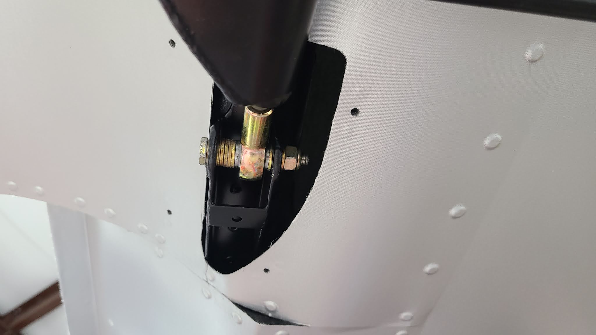
However, there was another task I needed to complete first. I needed to adjust the trailing strut rod bearing on the right wing. The wing adjustments needed to be finalized before mounting the wing tanks. That is why I hadn't bolted them in. When I put the struts on the wing before mounting I wasn't able to set the rod end correctly. So, with the wings finally in level attitude I was able to support the left wing while lifting the right wing to take the pressure off the bolt so I could remove it and adjust the rod end bearing. Once adjusted, I was able to relieve the pressure enough to reinsert the bolt with the proper spacer washers and tighten it for good. I had to preform the same procedure on the left wing. Now both wing struts are adjusted and have been final torqued.
Right Wing Rod End Bearing with washer spacers
Left Wing Rod End Bearing with washer spacers
Not really exciting but crucial.
Now I could get back to installing the wing tanks. It is a trial and error proposition. The object is to get the compression tubes, that the tanks bolt to, to be level with the flanges on the tanks. NOT level with the ground. Each compression tube bolts in two places, fore and aft. There are washers the are placed under or over each end of the tube to accomplish this leveling. One places the washers fore and aft, in the quantity that looks sufficient, mount the tanks to see if the flanges sit level on the tubes, if not, pull the tank out and try again. This goes on until the flanges and tubes have no gaps, or as close as possible. The reason for this circus is so no warp or twist is induced on the tanks when bolted in, preventing stress and leaks. It is a time consuming task preformed while balancing atop a ladder reaching over the wing, lifting the tanks in and out multiple times, three time each side to be exact. NOT a good time. I also didn't snap any action pics of this. However, it is done, the tanks are mounted.


I was able to get the left wing tank installed and rerouted the wiring back into the position that Chris had it. That's when it hit me, if I have any problem with the tanks I won't be able to remove them without cutting wiring. Not good. I called it quits for the evening after getting the right wing tank installed. I would get the left one tomorrow.
This morning I got the left tank leveled and installed while waiting for Chris to show up. When he arrived, I told him about the problem of the wire routing and tank removal. I originally had expressed a wish to be able to remove the wings without having to cut wiring. Way back when, we gave some thought to it and I actually purchased some cannon plugs in an effort to develop a way of splitting the wires at the wing. I eventually abandon the idea and moved on to other construction tasks.
So, here we were again and I had spent last evening thinking on it again. I came up with the idea of a D-Sub connector, like a printer plug, and wondered if it might be a workable solution? We talked about it and agreed that not being able to remove the "removable" wing tanks without cutting wires was a problem. After some discussion and fiddling, we set about making a bracket for a D-Sub connector and mounting it. It seems to be a workable solution providing a way to not only remove the wing tanks but the wing itself without cutting wires. That is huge. I gave Chris the go ahead and he cut the wire bundle and started preparing it for the D-Sub connector.
First attempt for the right wing with 1/2 of the connector in place, had to order the mounting hardware.
Without the connector
The larger one is the second iteration for the left wing.
A couple of shots of the wires in the connector on the right wing. The above bracket is not installed yet nor are the wires weather proofed. The above bracket goes to the right of the plug in the pic, you can see two small screw holes between the large lightening holes that the bracket uses. To the right and up at the top of the rib, you can see the two side by side holes in the tank, one for a vent and the other for the fuel gauge tubing. Note: the butt rib is not in place in these pics. You can see the stand offs for the butt rib, the gray vertical ovals with two screw holes on each end of the rib
The last project for today was to fab a tray for the engine ECU and temporarily install it. It's pushed back to allow for the large cable that attaches to it. This will allow some flexibility in routing the cable though the firewall. It also can be swapped to the other side of the fuselage or, it can be mounted upside down if necessary.